
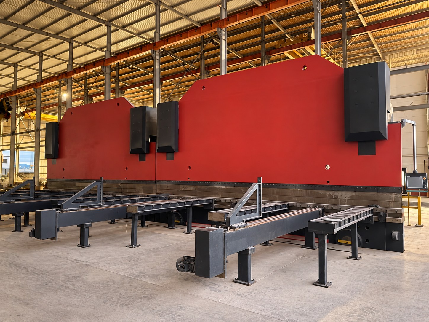
A long, heavy steel part can meet every flat-pattern dimension and still fail at assembly if its bends do not hold line, angle, and repeatability across the full length. That is the production problem 2400 ton press brake forming is intended to solve: applying controlled force over large parts while managing material behavior, tooling, handling, and downstream fit-up as one coordinated process.
For OEM and industrial programs, press brake capacity is not simply a tonnage specification. The useful question is whether the forming operation can produce the required geometry at the required length, in the required material, with a process that remains stable from first article through recurring production. This matters for truck frame components, freight rail structures, transformer tanks, equipment frames, and data center assemblies where a bend is often the feature that establishes the part’s final load path and mating surfaces.
What 2400 Ton Press Brake Forming Changes
A 2,400-ton CNC press brake with a 53-foot forming length expands the range of parts that can be formed without dividing them into smaller sections. Fewer segmented pieces can mean fewer weld joints, less weld distortion, and fewer opportunities for dimensional variation to accumulate along a long assembly.
That does not mean every long part should be formed as one piece. Plate thickness, grade, bend geometry, available die openings, handling limits, shipping constraints, and final assembly requirements all affect the right manufacturing route. In some cases, a fabricated weldment is the more practical solution. In others, a single long formed component offers a clearer path to structural consistency and lower downstream processing.
The central advantage is control. A heavy-duty press brake makes it possible to form substantial plate and long profiles while maintaining a planned relationship between bend location, flange length, angular tolerance, and datum features. CNC control supports repeatable ram positioning, but the machine is only one part of the result. Material condition, tooling selection, setup discipline, and inspection methods determine whether that capability reaches the finished part.
Tonnage Is Only One Part of Forming Feasibility
Press brake tonnage must be evaluated against the actual job, not read as a blanket capacity claim. Required force changes with material tensile strength, thickness, bend length, die opening, punch radius, and forming method. High-strength material can require significantly more force than mild steel at the same thickness and length. A tighter bend radius or narrower die opening may also increase tonnage demand.
Long-part forming introduces another consideration: load distribution. The force must be appropriate across the working length, and the tooling arrangement must support the required bend without overloading a localized section. Engineers reviewing a forming request should establish the material specification and actual bend lengths early, particularly when drawings include interrupted bends, formed tabs, cutouts near the bend line, or multiple bends that change how the part sits in the tooling.
Air bending, bottoming, and coining are not interchangeable choices. Air bending provides flexibility and is widely used for controlled production bending, but final angle is influenced by material variation and springback. Bottoming can improve angular consistency in suitable applications, while coining requires much higher force and is not the default solution for heavy long parts. The appropriate method depends on tolerance, material, part geometry, and production volume.
Designing Parts for Large-Scale Press Brake Forming
A manufacturable drawing gives the forming team enough information to establish a reliable sequence before production begins. Bend direction, internal radius, finished dimensions, material grade, and tolerance zones are fundamental. So are the less obvious details: which surfaces are functional datums, which flanges locate a later weldment, where cosmetic requirements apply, and whether the component will receive machining or coating after fabrication.
Bend sequence deserves early attention. A part with several flanges may be possible to form, but a later bend can interfere with the punch, die, backgauge, or previously formed features. The sequence may require specialized tooling, staged forming, or a revision to flange dimensions. Evaluating these conditions before material is cut prevents a common source of delay: discovering that a theoretically correct flat pattern cannot be safely or consistently formed with the intended setup.
Bend allowance and bend deduction also need validation against the actual material and tooling condition. Calculated values provide a starting point, but production-ready values are typically confirmed through setup trials and first-article measurement. Material thickness variation, grain direction, coating condition, and yield strength can all affect the final result. For a component that will mate to a machined or welded assembly, a small angular difference can become a meaningful positional error at the end of a long flange.
Long parts require a practical handling plan as well. Operators need controlled support during loading, forming, rotation, and unloading so the part is not damaged or allowed to sag in a way that compromises safe handling or measurement. Part weight, center of gravity, and edge condition affect this plan. Material movement is not separate from quality control – it is part of the process that protects formed geometry.
Forming Must Be Planned with Cutting, Welding, and Inspection
The strongest forming results come from an integrated route, not an isolated brake operation. Laser cutting determines edge quality, hole location, and blank dimensions before the part reaches the press brake. Those features influence bend placement and can affect how a component locates in later fixtures. For long components, a 16-meter laser bed paired with 53-foot press brake capacity can support a continuous workflow for parts that would otherwise need to be segmented.
The order of operations also affects weld quality and distortion control. Forming before welding can establish a repeatable profile and reduce the amount of post-weld correction needed. In other applications, welding must precede a final forming operation to achieve the intended structure. Neither route is automatically better. The decision should reflect weld access, heat input, joint design, required straightness, and how the assembly will be inspected.
For example, a long truck or industrial equipment member may include cut features, multiple formed sections, reinforcing elements, and machined interfaces. The manufacturing plan should define which dimensions are controlled from the flat blank, which are verified after forming, and which are confirmed only after welding and machining. Treating all dimensions as though they can be held at every stage without reference to process sequence creates avoidable inspection disputes.
At IONSA, large-part forming is supported within a broader fabrication workflow that includes cutting, welding, machining, dimensional verification, and finishing. That combination is relevant when a customer needs accountability for the completed component or assembly, rather than a formed blank transferred between multiple suppliers.
Verification After the Bend
Inspection of a formed part should be tied to functional requirements, not limited to checking a nominal angle. A reliable inspection plan may verify bend angle, flange width, overall length, straightness, twist, hole-to-bend position, and datum relationships. The right measurement approach depends on part size and tolerance requirements. A simple angle check can be adequate for a noncritical bracket; it is insufficient for a long component that must locate into a welded frame or rail assembly.
First-article validation is particularly valuable when a program involves unusual material, long bends, tight interfaces, or repeat production. It confirms the flat pattern, tooling, sequence, handling method, and measurement plan before the process is released for volume. If adjustments are required, they can be made with documented intent rather than through inconsistent floor-level correction.
Repeatability also depends on identifying the variables that must be controlled between lots. These can include material source and grade, thickness range, bend tooling, programmed angle compensation, backgauge reference, and inspection frequency. A program with demanding traceability requirements may need material documentation and inspection records carried through the complete fabrication route.
Information That Supports a Productive Forming Review
A meaningful manufacturing review starts with more than a PDF drawing. Provide the material specification, thickness, part length and weight, annual or release quantities, and required delivery schedule. Identify critical dimensions, cosmetic surfaces, weld requirements, machining interfaces, coating requirements, and any inspection documentation needed for acceptance.
It also helps to state the problem the part must solve. If the objective is to eliminate a weld seam, improve frame straightness, reduce assembly time, or consolidate suppliers, that context helps determine whether a long formed component is the correct approach. The best forming plan is not defined by tonnage alone. It is defined by whether the formed part reaches welding, machining, inspection, coating, and final delivery without creating a new constraint somewhere else.
For large steel components, the useful outcome is a production route that protects geometry from the first cut through final shipment. Reviewing drawings, volumes, dimensions, component weight, and delivery requirements together gives the forming operation a clear role in that result.