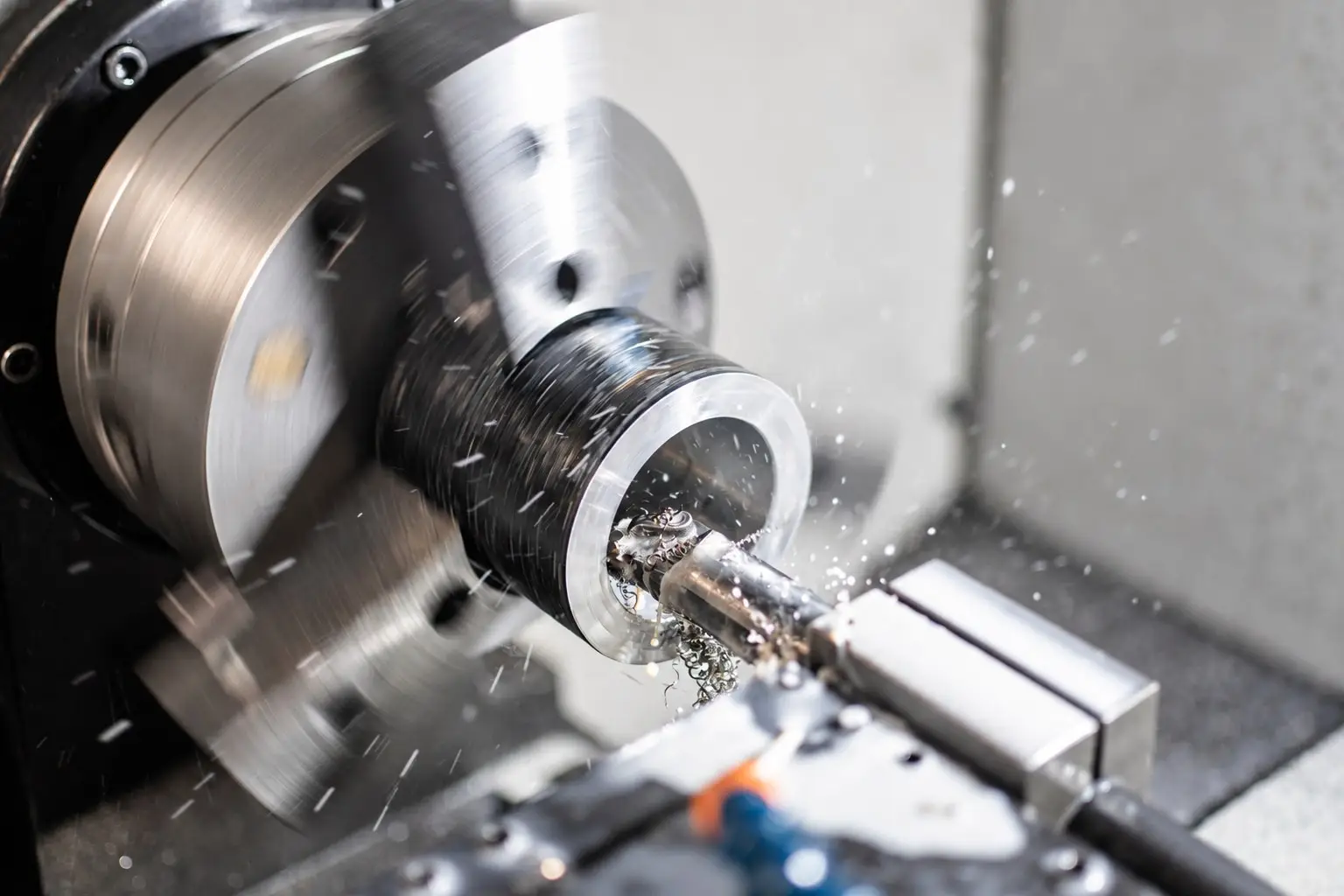
A welded structure can meet its individual part dimensions and still fail at final machining. Heat input, weld sequence, fixturing, material variation, and handling can all move critical features after welding. For OEMs, CNC machining welded assemblies is therefore not simply a machining purchase order added to a fabrication job. It is a controlled manufacturing process that must be planned from cut blank through final inspection.
This distinction matters most for heavy truck frame rails, large subassemblies, transformer tanks, freight rail components, and structural systems where machined interfaces must align with mounting points, mating parts, or downstream assembly fixtures. The supplier must manage both the welded condition of the assembly and the datum structure used to machine it.
Why welded assemblies need a different machining plan
Machining a plate or bar stock component starts from a relatively stable workpiece. A welded assembly is different. It includes multiple parts, weld metal, localized thermal effects, residual stress, and potentially long unsupported spans. The assembly can distort during welding, settle after unclamping, or shift when it is supported differently in a machining fixture.
That does not mean every fabricated structure requires extensive post-weld machining. The right approach depends on the function of the part. A large fabricated support with noncritical clearance holes may only need localized cleanup. A heavy truck rail or subassembly with machined mounting faces, precision hole patterns, and controlled rail geometry requires a more deliberate process.
Engineering teams should identify which features establish fit and function. These commonly include mounting pads, bearing surfaces, hole locations, threaded features, interface faces, and datum points used in vehicle or equipment assembly. Features that only provide clearance or cosmetic finish should not automatically receive the same machining requirement. Clear drawing definitions help control cost while protecting the dimensions that matter.
Establish datums before the first weld
The strongest machining strategy begins before parts reach a welding station. Fabrication and machining personnel need a shared understanding of the assembly datums, critical characteristics, weld sequence, and final machining access. If the final drawing references a surface that cannot be consistently located after welding, the process becomes difficult to repeat.
A practical approach is to establish stable datum features in the component design and fixture concept. Depending on the part, this may involve temporary locating features, machined setup pads, reference holes, or defined contact points that remain accessible through welding and machining. The goal is not to force every fabrication dimension to a machine-shop standard. The goal is to create a repeatable relationship between the welded assembly and the features that must be machined.
For long components, support strategy is equally significant. A frame rail or rail-related structure can react to gravity and clamping force across its length. The machining fixture should support the component in a condition that reflects its intended measurement and assembly state. Excessive clamping can temporarily force an assembly into position, then allow it to move when released. That can produce acceptable machine readings but unacceptable installed fit.
Welding sequence affects machined results
Welding sequence is often treated as a fabrication detail, but it directly affects machining results. Alternating weld locations, balancing heat input where appropriate, and using a defined fixture sequence can help manage distortion. The appropriate method depends on material thickness, joint design, weld process, component geometry, and production volume.
The key is consistency. A production assembly should not receive a different weld order, fixture condition, or handling method from one unit to the next without evaluating the effect on final dimensions. When a part will be machined after welding, process discipline becomes part of dimensional control.
CNC machining welded assemblies requires the right capacity
The work envelope of fabrication equipment determines what can be produced efficiently before machining begins. For long chassis rails and large fabricated structures, equipment capacity can reduce the need for unnecessary splices, secondary handling, or segmented forming strategies.
IONSA operates a 2,400-ton CNC press brake with a 53-foot forming length and a 30 kW fiber laser with a 16-meter cutting bed. For qualifying OEMs, those capabilities are relevant because long formed and cut components can be prepared within a production flow designed for heavy assemblies. The available capacity should always be evaluated against the drawing, material grade, thickness, bend requirements, part weight, and annual volume.
Welding capacity also matters beyond the raw number of stations. A supplier with 150+ welding stations can support multiple fabrication operations, but buyers should confirm how work is routed, how fixtures are controlled, and how inspection requirements are incorporated into production. Capacity without documented process control can create variation. Controlled capacity supports repeatability when production schedules increase.
Machine access and part handling must be reviewed early
A machined feature is only useful if the cutting tool can reach it while the assembly is securely supported. Deep pockets, internal faces, close-spaced gussets, and boxed sections can restrict access. Large components also require safe loading, positioning, rotation, and unloading without damaging reference surfaces.
These issues should be reviewed during manufacturability evaluation, not after the welded assembly arrives at the machining area. A supplier may recommend a change to weld access, gusset position, hole sequence, datum selection, or machining allowance. Such changes are not necessarily design compromises. When they preserve functional requirements, they can reduce rework and improve repeatability.
Inspection should follow the functional datum scheme
Inspection for welded and machined work must distinguish between fabrication dimensions and final functional dimensions. Measuring a welded assembly from convenient edges may be useful for process checks, but it may not verify the relationships that affect customer assembly.
The inspection plan should reference the same datums used for final machining whenever possible. This creates a direct connection between how the part is located, how it is machined, and how it is accepted. For large components, portable dimensional inspection equipment can provide practical verification of features that are difficult to inspect on a fixed measuring system.
Creaform dimensional inspection equipment can support measurement of large fabricated and machined structures when applied under an appropriate inspection plan. Results should be documented at the level required by the customer, whether that includes first-piece review, in-process checks, final reports, or defined critical-feature records.
Weld quality must be considered alongside dimensional results. An in-house AWS Certified Welding Inspector provides a qualified resource for welding inspection activities, while AAR M-1003 certification is relevant to organizations evaluating production controls for freight rail applications. Buyers should still define their required weld acceptance criteria, documentation, material traceability, and any customer-specific quality provisions in the purchase package.
What OEMs should provide for an accurate review
A complete request for quotation reduces assumptions before production begins. Drawings should identify critical dimensions, datums, weld symbols, material specifications, machining requirements, and applicable inspection criteria. Models are helpful when available, particularly for assemblies with complex interfaces or long structural geometry.
OEM teams should also provide expected quantities, component weight, overall dimensions, delivery schedule, packaging needs, and any requirements for material or process documentation. If the assembly mates with an existing vehicle frame, tank, railcar structure, or equipment base, information about the functional interface can be more valuable than a generic tolerance note.
For new programs, it is useful to discuss whether final machining is intended to correct normal welding movement, create precision interfaces, or both. That conversation affects fixture design, machining allowance, inspection points, and the order of operations. For repeat programs, previous quality concerns or assembly issues should be included early so the manufacturing plan addresses the actual source of variation.
A capable supplier will not assume that machining can solve every fabrication issue after the fact. Excessive distortion may require revised fixturing, welding sequence changes, design adjustments, or material handling controls. Conversely, applying machining to every surface can add cost without improving field performance. The right balance comes from matching process controls to the features that control fit, safety, and assembly function.
When sourcing CNC machining welded assemblies, provide the drawing package, quantities, overall dimensions, component weights, and delivery requirements for an engineering-informed manufacturing review. That early review is where a welded structure becomes a repeatable production component rather than a part that must be corrected after it reaches final assembly.
Discuss your production requirements
Explore IONSA’s Heavy truck subassembly fabrication. Request a quote and upload your drawing with the current revision, material, quantities, overall dimensions, component weight, delivery schedule, and required inspection records. IONSA will review drawing-specific feasibility before confirming tolerances, capacity, or lead time.