A heavy fabricated part can meet material and welding requirements yet still create an expensive problem at assembly. A rail, frame component, transformer tank panel, or structural weldment that is slightly out of position may prevent fit-up, complicate downstream machining, or require unplanned rework. Dimensional inspection for steel fabrications provides the evidence that critical features remain aligned with the drawing after cutting, forming, welding, and handling.
For OEM sourcing and quality teams, inspection is not simply a final acceptance activity. It is a manufacturing control function. The most useful inspection plan identifies which dimensions govern assembly, establishes practical datums, and checks the part at process stages where correction is still feasible.
What dimensional inspection must control
Heavy steel fabrications have different inspection risks than small precision-machined parts. Long components can move during handling. Heat input from welding can change flatness, straightness, hole location, and the relationship between formed or machined features. The larger the assembly, the more consequential a small angular or positional variation can become at a remote feature.
The drawing should determine the inspection approach. Overall length and width may matter, but they are rarely sufficient. Critical requirements commonly include hole patterns, mounting interfaces, formed angles, rail profiles, flange position, frame cross-member locations, flatness, straightness, and the relative position of welded features. A useful dimensional report connects those requirements to the specified datum structure rather than collecting measurements that do not predict assembly fit.
This distinction matters on heavy truck frame rails and subassemblies. A long rail may be cut and formed accurately, but downstream assembly can still be affected if brackets, holes, or reinforcements shift relative to the primary rail datum. The same principle applies to transformer tanks, where panel relationships and mounting interfaces affect final assembly, and to large freight rail components that must conform to controlled interfaces.
Establish datums before production begins
Dimensional control begins during drawing review, not after welding is complete. Engineering and quality teams should determine how the part will be located during fabrication and how it will be located by the customer at assembly. Those references should be compatible whenever practical.
A datum scheme for a heavy fabrication often starts with a stable primary plane or surface, followed by a secondary edge, centerline, hole, or machined feature. The best choice depends on the product. A formed frame rail may use its web and selected hole features as functional references, while a welded structure may need fixture reference points that correspond to mounting surfaces or machined interfaces.
Not every dimension needs the same level of control. It depends on the function of the feature, the manufacturing process, the inspection method, and the consequences of variation. Critical-to-fit dimensions deserve defined measurement methods and appropriate checkpoints. Less critical overall features can be managed with a different approach. Treating all dimensions as equally sensitive can add inspection effort without improving the part’s functional quality.
Dimensional inspection through the fabrication process
Final inspection is necessary, but it cannot recover time lost when a dimensional issue is found after all welding, machining, and finishing operations are complete. Process-stage checks provide earlier feedback and help isolate the source of variation.
Cut and formed components
The first meaningful checks usually occur after laser cutting and forming. For long rails, large panels, and structural members, operators and inspectors can verify critical cut features, hole locations, formed profiles, and bend relationships before the components move into assembly.
IONSA’s 30 kW fiber laser with a 16-meter cutting bed and 2,400-ton CNC press brake with 53-foot forming length support the processing of long, heavy components. For these parts, measurement planning must account for length as well as feature relationship. A component that is correct near one end but accumulates variation over a long distance can still create a fit-up issue in a multi-part assembly.
Fit-up before welding
Fit-up inspection confirms that components are positioned correctly before weld sequence and heat input can make adjustment more difficult. The focus may include locating holes, bracket spacing, diagonal relationships, flange offsets, and interface positions. Fixture condition is part of this control. A capable fixture supports repeatable location, but it should be verified rather than assumed to be accurate indefinitely.
For repeat production, first-piece inspection is especially valuable. It establishes that the program, fixture, material condition, and setup are producing the intended geometry before a larger quantity proceeds. When a part family includes multiple similar configurations, clearly identifying revision level and fixture configuration helps prevent an otherwise correct inspection from being applied to the wrong variant.
Post-weld and final verification
Welding can introduce localized distortion or movement across a large assembly. The appropriate post-weld checks depend on the component and its intended next operation. A fabrication that will be machined may need confirmation that sufficient stock, access, and feature position remain available. A finished weldment may require a more complete verification of customer-defined interfaces.
With 150+ welding stations and an in-house AWS Certified Welding Inspector, IONSA can align welding quality oversight with the dimensional requirements that affect production acceptance. Welding inspection and dimensional inspection address different questions, but they should work together. A weld can meet its acceptance criteria while the overall assembly still needs dimensional confirmation.
Using Creaform equipment for large-scale measurement
Large fabricated assemblies often require more than tape measures, calipers, and fixed gauges. Conventional tools remain effective for many direct checks, particularly when the drawing calls for simple linear dimensions. Their limitation is that they may not show how multiple features relate across a long or complex structure.
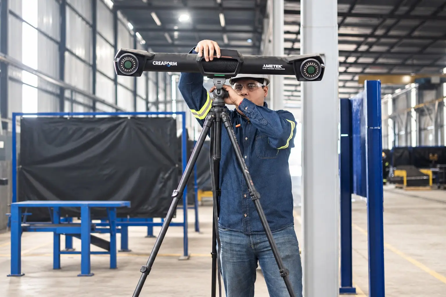
IONSA’s Creaform portable CMM and 3D scanning equipment can support comparison of measured geometry against the required design condition for suitable parts and inspection plans. This is particularly useful when the objective is to evaluate multiple interfaces, capture positional relationships across a large assembly, or investigate a recurring fit-up concern. The value is not the equipment alone. It comes from using the measurement results against defined datums, drawing requirements, and an agreed acceptance method.
For production work, a full-dimensional capture is not always the right answer for every unit. It may be appropriate for first articles, first-piece verification, complex assemblies, engineering investigations, or periodic validation. Repeated production parts may benefit from a targeted inspection plan that concentrates on the features most likely to affect assembly. The right balance depends on volume, part complexity, risk, and customer documentation requirements.
Documentation that supports supplier qualification
OEM teams need inspection records that are understandable and connected to the part being supplied. At a minimum, records should identify the component, drawing or revision level, inspected characteristics, actual results, acceptance status, and the measurement method or equipment used where required. Traceability is stronger when the documentation also connects to production order information and relevant material or process records.
For rail-related programs, AAR M-1003 certification may be a relevant factor in supplier qualification. For any heavy fabrication program, purchasing and quality teams should clarify inspection deliverables before production release. Requirements may include first-article documentation, first-piece approval, in-process records, final dimensional reports, weld documentation, or customer-specific formats. Agreeing on these expectations early reduces conflicting interpretations after parts are complete.
MIETrak ERP supports production visibility and record control within the manufacturing process. Combined with defined dimensional checkpoints, this helps create a clearer connection between the drawing, the work performed, and the inspection evidence associated with the finished part.
Start with the features that drive assembly
A productive manufacturing review starts with the current drawing, quantity, component dimensions, weight, required delivery schedule, and the interfaces that matter most at final assembly. If there are known fit-up issues, prior inspection reports, mating-part information, or customer-specific quality requirements, those details should be included as well.
The practical goal is not to inspect more dimensions than necessary. It is to verify the dimensions that determine whether a heavy fabrication can move predictably into the next operation and assemble as intended. That is the standard an inspection plan should serve.
Discuss your production requirements
Explore IONSA’s Heavy truck subassembly fabrication. Request a quote and upload your drawing with the current revision, material, quantities, overall dimensions, component weight, delivery schedule, and required inspection records. IONSA will review drawing-specific feasibility before confirming tolerances, capacity, or lead time.