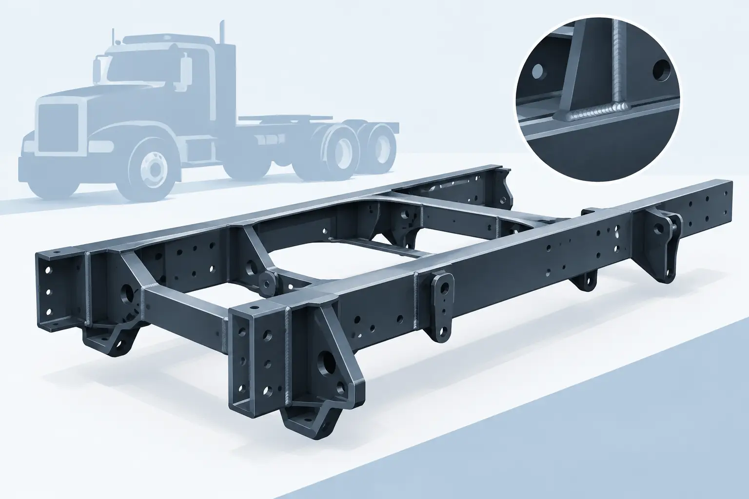
A welded subassembly example for a heavy truck frame is more useful when it shows the production decisions behind the welds, not just the finished part. For an OEM buyer or manufacturing engineer, the key questions are whether the assembly can be produced repeatedly, controlled against the drawing, inspected appropriately, and delivered in the required program sequence.
Consider a representative heavy truck crossmember assembly. It may include a formed structural member, laser-cut reinforcement plates, brackets, gussets, and mounting features welded into a controlled fixture. The assembly has to fit a larger rail-frame system, so hole locations, bracket orientation, weld access, distortion management, and inspection points all matter. A part can appear sound on the shop floor and still create downstream issues if its mounting interfaces do not match the mating rails or components.
What this welded subassembly example includes
In this example, fabrication begins with a released drawing package that identifies material grade, cut profiles, formed geometry, weld symbols, critical dimensions, and any customer-specific inspection or marking requirements. The supplier’s engineering review should identify what is controlled by the incoming material, what is controlled by cutting and forming, what requires fixture location, and what must be verified after welding.
The process generally starts with plate and structural components cut to profile. For long or large parts, bed length can be as relevant as laser power because material handling and nest layout affect practical production flow. IONSA operates a 30 kW fiber laser with a 16 m cutting bed, which supports processing of long components used in truck chassis and heavy fabricated assemblies. The equipment rating does not establish feasibility for a specific part. Final feasibility depends on material, thickness, geometry, edge condition, tolerances, quantity, and drawing requirements.
Formed components are then prepared where the design calls for channels, flanges, brackets, or stiffeners. A 2,400-ton CNC press brake with a 53 ft forming length provides capacity for long formed components, including chassis-related sections. Whether a part can be formed in one hit, requires staged forming, or needs a different manufacturing approach must be evaluated from the drawing and material details.
After cutting and forming, parts move to fit-up. This is the stage that determines whether the assembly is built from a common datum strategy rather than adjusted to fit after welding. A suitable fixture can locate primary interfaces while allowing access for required welds. For a crossmember, locating from designated mounting holes or machined reference surfaces may make more sense than locating from raw outside edges. The correct approach depends on the functional datums defined by the customer drawing.
Welding decisions that affect frame assembly fit
Welding joins the components, but it also adds heat and potential movement. In heavy truck subassemblies, distortion is not merely cosmetic. A shift in bracket position or crossmember profile can affect assembly at the OEM plant, introduce stress during bolting, or require rework in the field.
A practical welding plan considers joint type, weld sequence, fixture restraint, access, and inspection requirements together. Alternating weld locations or sequencing opposing joints can help manage heat input and movement. However, the correct sequence is specific to the component design. Excessive restraint can also create problems, so the goal is controlled fabrication rather than simply clamping every feature as tightly as possible.
Weld symbols should be reviewed before production begins. Questions worth resolving include whether all-around welds are truly required, whether intermittent weld spacing is clear, whether weld size is compatible with joint access, and whether cosmetic finishing is needed on visible or mating surfaces. These details affect cycle time, consumable use, inspection planning, and the potential for distortion.
IONSA has more than 150 welding stations and an in-house AWS Certified Welding Inspector. The AWS CWI supports weld inspection activities within the facility; it does not mean that every weld receives independent third-party certification. Inspection scope should be defined by the drawing, applicable code requirements, customer specifications, and the agreed quality plan.
A useful inspection plan follows the risk
Not every dimension needs the same inspection method or frequency. A heavy truck welded subassembly commonly has three types of characteristics: features that establish fit to the frame rail, features that locate attached equipment, and general dimensions that define the part envelope. The first two groups usually deserve the closest control because they drive functional assembly.
For an initial production part or a new revision, dimensional inspection may include confirmation of overall length and width, bracket locations, mounting-hole patterns, formed angles, and reference surfaces after welding. Creaform dimensional inspection equipment can support measurement under an agreed inspection plan. The appropriate inspection method, sampling frequency, and acceptance criteria remain program-specific.
Visual weld inspection is typically part of the process, with additional testing considered when required by the applicable specification or customer documentation. Clear records should show what was inspected, how nonconformities were handled, and what revision of the drawing governed production. This is especially valuable when a frame program includes multiple similar assemblies that differ only in hole pattern, bracket position, or reinforcement configuration.
Repeatability depends on more than welding capacity
A supplier may have enough welding stations to support volume, but repeatable manufacturing requires control before the first arc is struck. Material identification, cut-part segregation, formed-part verification, fixture condition, weld procedure use, and final inspection all contribute to consistent output.
Production records can also matter during OEM supplier qualification. MIETrak ERP supports production records at IONSA, while the depth of traceability should be aligned to the specific program. A prototype order may require a different documentation package than a recurring production release. Buyers should specify whether they need material certifications, inspection reports, weld documentation, lot control, serialization, packaging requirements, or other traceability elements before quoting is finalized.
For programs involving rail components, transformer tanks, or data center structures, the same principle applies: the assembly must be designed around its functional interfaces. A large rail structure may prioritize long straightness, mounting geometry, and controlled weld sequence. A transformer tank assembly may require customer-specified coating and enclosure requirements. Where IEEE C57.12.28-related requirements apply to pad-mounted equipment enclosures, those coating and integrity requirements should be reviewed against the customer specification rather than assumed as a blanket certification.
IONSA’s AAR M-1003 certification is relevant to quality assurance activities within its defined facility and activity scope. For a freight rail program, buyers should confirm that the planned scope, records, inspection requirements, and customer approvals align with the needs of the specific component.
Information to provide for a manufacturing review
The strongest welded subassembly example begins with a complete technical package. A drawing alone may not communicate program risks if it omits revision status, material requirements, critical characteristics, weld details, or inspection expectations. Providing this information early allows the fabricator to assess manufacturability and build a quote around the actual requirement rather than assumptions.
For heavy truck frame rails and welded subassemblies, provide the released drawings and revision level, material specification, annual or release quantity, overall dimensions, estimated component weight, requested delivery schedule, and inspection requirements. Include any required fixture approval, first-article expectations, weld procedure requirements, packaging instructions, and documentation needs. If the part mates to customer-supplied rails or assemblies, identify the functional datums and any critical interface conditions.
This level of detail helps distinguish a part that is technically weldable from one that is ready for repeatable production. It also gives engineering, quality, purchasing, and program teams a common basis for evaluating cost, capacity, inspection, and risk.
A well-defined welded subassembly is not simply a group of parts joined together. It is a controlled interface within a larger vehicle or equipment system. To review a heavy truck frame rail or welded subassembly requirement, submit drawings, material, quantity, dimensions, weight, schedule, and inspection requirements at https://ionsamx.com/#request-quote.