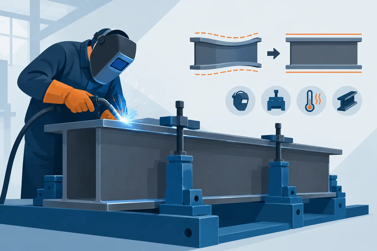
A long truck frame rail that leaves a fixture straight can move significantly after welding if heat is concentrated in the wrong sequence. The same risk applies to heavy truck subassemblies, transformer tanks, large rail components, and data center structures. Knowing how to control weld distortion starts before the first arc is struck: it requires a process plan that considers material condition, joint design, restraint, heat input, weld sequence, and inspection.
Distortion is not simply a welding-floor issue. For OEM purchasing, manufacturing engineering, and quality teams, it can affect assembly fit, downstream machining, coating preparation, inspection effort, and delivery performance. The goal is not to eliminate all thermal movement, which is rarely realistic in fabricated steel. The goal is to predict it, manage it, and produce parts within drawing requirements consistently.
Why weld distortion occurs in heavy fabrication
Welding creates a localized heating and cooling cycle. Steel expands as it is heated, then contracts as the weld and adjacent heat-affected zone cool. Because the heat is not applied uniformly across the part, contraction forces pull the assembly out of its original shape.
The resulting movement commonly appears as angular distortion, longitudinal shrinkage, transverse shrinkage, bowing, twisting, or local buckling. A long member may pull upward along a weld line. A plate assembly may dish or develop a corner lift. On a heavy truck frame rail, even relatively small movement can complicate hole alignment, bracket placement, or later assembly operations.
Part mass alone does not prevent distortion. Heavy sections can resist movement better than thin plate, but long welds, unbalanced joints, high restraint, and inconsistent fit-up can still introduce significant residual stress. The drawing geometry, weld symbols, material grade, and sequence all determine the appropriate control plan.
Control distortion through design and pre-weld planning
The most effective correction is often a prevention decision made during engineering review. Before production, the fabrication team should review datum strategy, joint access, weld size, weld location, assembly sequence, and the relationship between welded features and critical dimensions.
Use only the weld size required by the design
Oversized welds add unnecessary deposited metal and heat. They can increase shrinkage without adding value when the drawing or applicable code does not require the additional weld volume. Correct joint preparation and fit-up make it easier to achieve the specified effective throat without compensating for gaps through excessive welding.
This does not mean reducing weld size below the engineering requirement. It means treating weld size as a controlled design requirement, not a variable to be adjusted casually on the shop floor. For critical load-bearing subassemblies, any proposed change should follow the customer’s engineering and approval process.
Build a balanced weld layout where possible
Balanced welding reduces the tendency for one side of an assembly to pull against the other. If a design permits welds on opposing sides of a neutral axis, applying comparable weld volume in a balanced pattern can reduce angular movement. Intermittent welds may also reduce total heat input where they meet the drawing, service requirements, and applicable welding procedure.
Some designs cannot be balanced. A bracket welded to one face of a rail, a stiffener inside a transformer tank, or a one-sided access condition may inherently create an unbalanced thermal load. In those cases, the process plan needs stronger controls through fixturing, sequencing, presetting, or planned correction.
Establish fit-up before welding begins
Poor fit-up is a frequent source of avoidable heat input. Large root openings, inconsistent contact, mislocated parts, and unstable tack welds can require extra passes or rework. Each added weld pass changes the thermal profile and increases the chance of movement.
A repeatable fit-up process should identify reference surfaces, clamp locations, tack pattern, allowable gaps, and hold points for verification. For complex or long assemblies, the fixture is part of the manufacturing process, not simply a device for holding steel in place.
Manage heat input and welding sequence
Once joint design and fit-up are established, distortion control depends on how welding heat is introduced. The objective is to place sufficient weld metal with a controlled, repeatable thermal cycle while avoiding unnecessary concentration of heat.
Heat input is influenced by amperage, voltage, travel speed, welding process, bead size, interpass temperature, and the number of passes. The correct parameters depend on the approved welding procedure, base material, joint configuration, and required weld properties. A faster travel speed or smaller bead can reduce heat input in some situations, but only when fusion, profile, and procedure requirements remain satisfied.
Sequence welds to distribute contraction
Weld sequence is one of the most practical ways to control weld distortion. Rather than completing a long weld continuously from one end to the other, fabricators may use back-step, skip welding, or alternating-side sequences when the drawing and welding procedure allow them. These methods distribute heat and contraction instead of allowing one area to accumulate movement.
For example, a long stiffener on a heavy truck component may be welded in controlled segments, alternating locations to avoid pulling the rail progressively in one direction. A fabricated enclosure may be welded in a sequence that balances opposing corners and panels. The best pattern depends on the assembly, restraint, accessibility, and dimensional priorities.
Welding sequence must also account for final access. Closing an assembly too early can make it difficult to reach internal welds, inspect them, or correct fit-up. Production planning should identify welds that must be completed before a cover, panel, or structural member is installed.
Avoid excessive restraint
Clamping and strong fixtures are useful, but over-restraint can create another problem. If a part is prevented from moving entirely while weld metal contracts, high residual stresses can remain after unclamping. The part may then move unexpectedly, or stress concentrations may affect service performance.
The right approach is controlled restraint. Fixtures should locate the part from meaningful datums, resist predictable movement, and allow the process team to release clamps in a planned order. Where appropriate, presetting a component slightly opposite the expected pull can bring the final welded condition closer to nominal dimensions. Preset values should be established through qualified process development, not assumed from a similar-looking part.
Verify dimensions at the right process stages
Final inspection alone is too late to manage recurring distortion effectively. Dimensional checks should occur at defined stages: incoming material or cut blank verification when applicable, formed-part verification, fixture setup, post-weld inspection, and final release. The inspection plan should focus on the dimensions most sensitive to weld shrinkage, such as rail straightness, diagonal relationships, flange position, mounting-hole location, and assembly interface points.
For long chassis rails and large fabricated structures, the equipment used upstream matters. A 16-meter laser cutting bed can support long-part cutting, while a 2,400-ton CNC press brake with a 53-foot forming length supports forming of large components. Those equipment ratings do not determine whether a specific drawing is feasible. Drawing-specific material, geometry, weight, forming requirements, and inspection criteria still require engineering review.
IONSA can use Creaform dimensional inspection equipment under an agreed inspection plan to evaluate part geometry and document required results. Its in-house AWS Certified Welding Inspector supports welding inspection and process oversight. Production records in MIETrak ERP can support program-specific traceability requirements. For rail-related work, AAR M-1003 quality assurance certification applies within its defined facility and activity scope.
Treat correction as a controlled operation
Even with a sound process, some assemblies require controlled correction after welding. Mechanical straightening, pressing, or carefully planned thermal straightening may be appropriate when permitted by the material specification, customer requirements, and applicable procedure. The correction method must not damage the part, alter required properties, or conceal an underlying process problem.
Repeated straightening is a signal to revisit the root cause. Review weld size, fit-up variation, fixture condition, sequence adherence, material flatness, and the location of critical datums. A correction step may be acceptable for a stable, proven process, but it should not substitute for process control.
Start with the drawing and inspection requirements
For heavy truck frame rails and heavy truck subassemblies, distortion control should be defined alongside manufacturability, welding, and dimensional requirements before production is released. The same discipline benefits transformer tanks, large freight rail components, and data center steel structures, where panel flatness, connection geometry, and assembly interfaces can drive rework costs.
Submit drawings, material specifications, quantity, overall dimensions, component weight, production schedule, and inspection requirements for an engineering-informed manufacturing review. A clear process plan before welding gives both the fabricator and buyer a better basis for repeatable parts, practical inspection, and fewer late-stage dimensional surprises.