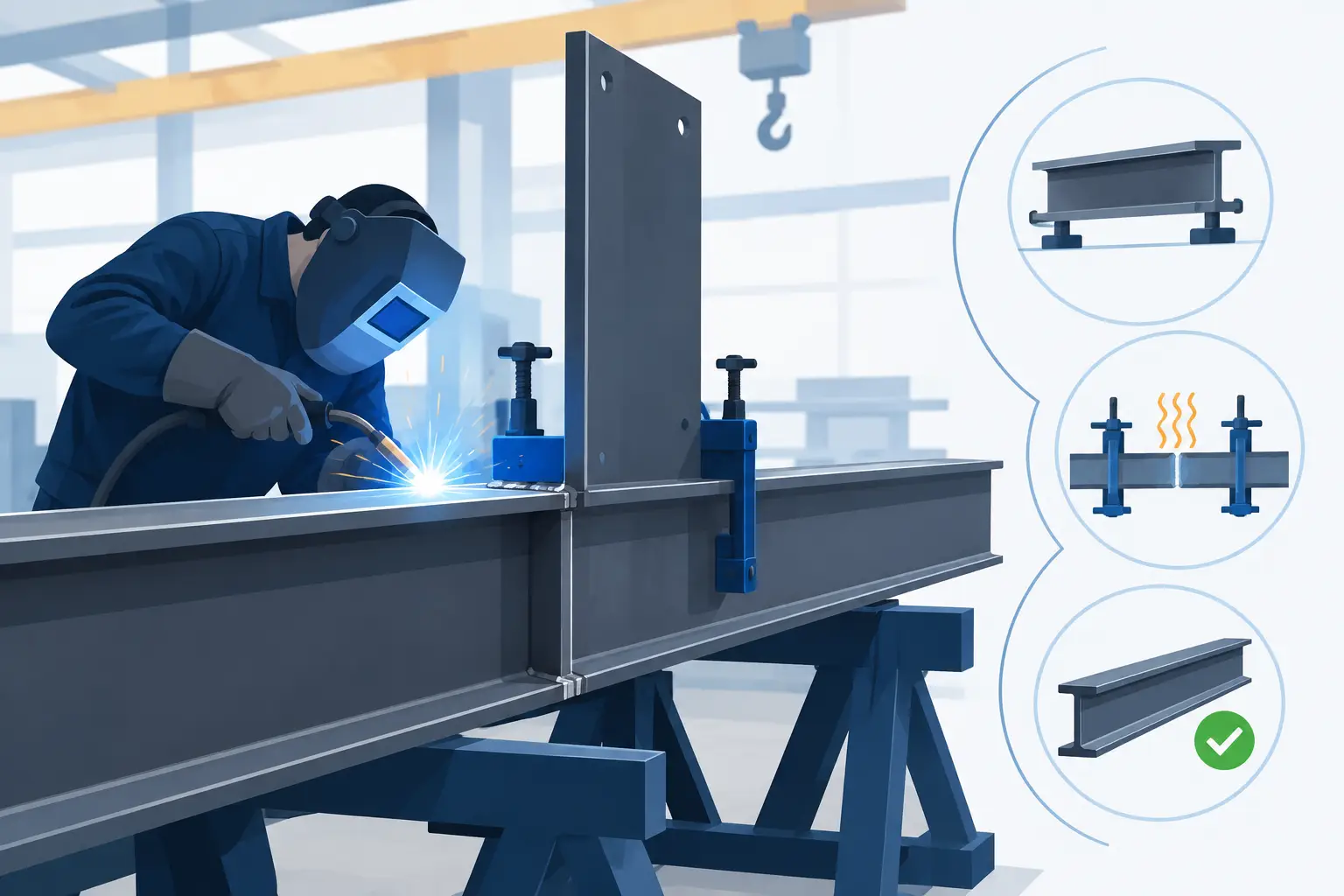
A heavy truck frame rail can be cut and formed accurately, then lose its intended geometry during welding. The same risk applies to heavy truck subassemblies, transformer tanks, large freight rail components, and data center structures. Preventing weld distortion is therefore not a final inspection activity. It is a manufacturing-control issue that starts with the drawing review and continues through fixturing, weld sequencing, cooling, and dimensional verification.
For OEM buyers and manufacturing engineers, the concern is straightforward: a welded assembly must fit downstream operations without unplanned rework, forced assembly, or compromised performance. The right approach depends on the material, joint design, weld size, part length, restraint method, and inspection requirements. No single welding technique eliminates distortion in every heavy fabrication program.
Why weld distortion develops in heavy assemblies
Welding introduces concentrated heat into a localized area. Material near the weld expands as it heats and contracts as it cools. When that contraction is uneven across the part, the assembly can pull, bow, twist, angle, or develop localized shrinkage.
Long members are particularly sensitive because small changes can accumulate over length. A heavy truck frame rail, for example, may be affected by weld placement, bracket spacing, crossmember attachment sequence, or the relationship between formed geometry and welded features. Large rail components and structural frames present similar issues when welds are concentrated on one side of a member or when joints are completed in an unbalanced order.
Part thickness does not remove the risk. Heavier sections may resist visible movement more than light-gauge material, but they can still develop angular distortion, residual stress, or dimensional change around connection points. Conversely, a design with intermittent welds or smaller weld sizes may reduce heat input, but only where those details meet the structural and customer requirements.
Preventing weld distortion starts before welding
The most effective controls are established before the first arc is struck. Engineering review should evaluate the weld symbols, specified weld sizes, joint access, part orientation, datum scheme, and any critical dimensions that could be influenced by welding. This is especially important when a component must fit mating parts supplied by another facility.
Fabrication sequence matters as much as individual weld quality. Where the drawing and approved welding requirements allow, balanced welding can distribute heat more evenly across an assembly. Alternating between sides, using a planned progression along a long member, and avoiding unnecessary concentration of welds in one area can reduce the tendency for a part to pull in one direction.
Weld size deserves disciplined attention. Oversized welds add heat, filler metal, cycle time, and contraction without necessarily improving the assembly. The correct objective is to produce the weld specified by the drawing and applicable procedure, not to add material as a precaution. Buyers should expect the fabricator to clarify ambiguous weld details before production rather than making assumptions on the floor.
Joint preparation also affects consistency. Variable gaps, poor edge condition, and inconsistent fit-up can require operators to add weld metal or change technique to complete a joint. That variation changes heat input from part to part. Stable laser-cut blanks, controlled formed parts, and repeatable fixture contact points support more predictable welding outcomes.
Fit-up and fixturing control the starting condition
A welding fixture cannot correct every incoming variation, but it establishes a repeatable starting position and controls how an assembly reacts to welding. For heavy subassemblies, fixture design should locate parts from functional datums rather than from convenient but noncritical edges whenever possible.
The balance is restraint without over-restraint. A fixture must hold components securely enough to maintain fit-up and alignment through the planned sequence. Excessive restraint, however, can trap stress in the assembly or make removal difficult after cooling. The appropriate approach depends on the mass of the parts, the number and location of welds, the joint configuration, and the allowable dimensional condition after welding.
Tack welds are part of this control strategy. They should hold the joint at the required gap and alignment while allowing the final weld sequence to proceed as planned. Inconsistent tack placement or size can introduce variation before production welding begins.
For programs with long or complex assemblies, first-article fixture validation is valuable. The fabricator can confirm that the part locates correctly, that weld access is practical, and that the planned sequence produces acceptable geometry. The lessons from this evaluation should be carried into documented work instructions and production records appropriate to the program.
Heat input and sequence must be managed together
Heat input is affected by welding process, amperage, voltage, travel speed, wire or electrode selection, joint configuration, and weld length. It should be controlled within approved welding procedures, but distortion planning requires looking beyond one weld at a time. The cumulative effect of multiple welds across the assembly is what often changes the final geometry.
A useful sequence places welds in an order that limits uneven shrinkage. On symmetrical parts, this may mean moving between opposing sides. On long components, it may involve welding from selected locations in stages rather than completing every weld continuously in one direction. The correct sequence must remain compatible with access, fixture design, approved procedures, and productivity requirements.
Interpass temperature and cooling practices may also affect results. Rushing a part through successive operations before it has stabilized can complicate dimensional evaluation. On the other hand, unnecessarily slow handling can reduce throughput. Production planning should set an appropriate point for inspection based on the assembly design and customer requirements.
Preheat, when required by the applicable welding procedure or material condition, is a welding-quality control and must be applied consistently. It is not a generic distortion remedy. Its effect on the full assembly should be considered alongside weld sequence, restraint, and total heat introduced.
Measure the assembly at the right stages
Final inspection alone identifies a problem after labor and material have already been added. In-process dimensional checks provide earlier feedback. Critical features can be checked after forming, after fit-up, after major welding stages, and at final completion, depending on the inspection plan.
For frame rails and heavy truck subassemblies, this may include checks of length, straightness, hole relationships, bracket position, and interfaces that affect downstream assembly. Transformer tanks may require attention to panel alignment, openings, flange condition, and features related to customer-specified coating requirements. Large rail components and data center structures often require verification of mating surfaces, attachment points, and overall geometry before shipment.
IONSA supports dimensional inspection with Creaform equipment under an agreed inspection plan. The appropriate measurement method, datum strategy, reporting format, and traceability depth should be defined for the specific program. MIETrak ERP supports production records, while the records required for a given part number should be established during program planning.
Match fabrication capacity to part geometry
Distortion prevention also benefits from selecting equipment that can process the part without unnecessary handling or pieced-together workarounds. A 30 kW fiber laser with a 16-meter cutting bed can support long blank preparation, while a 2,400-ton CNC press brake with 53 feet of forming length supports large formed components. Equipment ratings must still be reviewed against the specific drawing, material, dimensions, and forming requirements.
With more than 150 welding stations, IONSA can evaluate welding flow, fixturing needs, and inspection controls for production programs rather than treating welding as an isolated operation. Its in-house AWS Certified Welding Inspector supports welding oversight and inspection activities. This does not replace the need to define program-specific acceptance criteria, documentation, and customer quality requirements.
For additional equipment context, review IONSA’s heavy steel fabrication capabilities during supplier qualification.
Give the fabricator the information needed to control distortion
A meaningful manufacturing review needs more than a part name and annual volume. Provide current drawings, material specifications, quantity, overall dimensions, component weight, required schedule, and inspection requirements. Include weld procedures or customer standards when applicable, along with critical-to-function dimensions, datum references, mating-part information, and packaging constraints.
Request a quote through the IONSA website and provide those details for an engineering-informed review. Early discussion of weld sequence, fixture strategy, measurement points, and acceptance criteria gives both teams a better chance to prevent distortion before it becomes a production issue.
The most useful question is not whether a fabricator can weld the assembly. It is whether the manufacturing plan accounts for how that assembly will move as it is welded, measured, handled, and delivered.