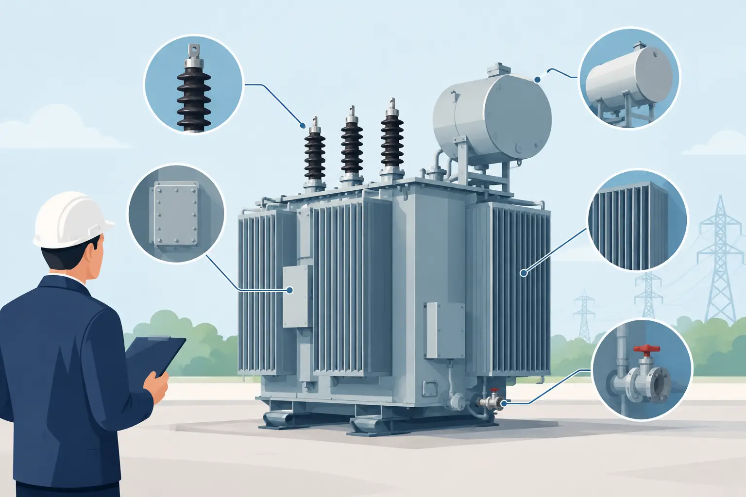
A transformer tank is not simply a welded steel enclosure. It is a structural, sealed, coated, and inspectable assembly that must support the electrical design while remaining practical to manufacture at production volume. The top transformer tank features for an OEM sourcing team are therefore the ones that connect drawing requirements to forming capacity, weld quality, dimensional control, handling, and documented inspection.
For purchasing and engineering teams, early supplier review is valuable because tank performance depends on details that can appear routine on a drawing: panel geometry, seam location, flange flatness, lifting provisions, radiators or accessory interfaces, and coating preparation. A fabricator should evaluate those details against the component size, material, quantity, handling needs, and inspection requirements before production begins.
Top transformer tank features that affect manufacturability
Large formed panels and controlled geometry
Tank bodies commonly rely on large formed steel panels, stiffened walls, base structures, and covers. Forming capability matters because panel design influences the number of seams, the location of welds, the consistency of mating edges, and the amount of post-form correction required.
IONSA operates a 2,400-ton CNC press brake with a 53-foot forming length. That capacity is relevant when a customer’s drawing calls for long formed sections or large structural elements. Equipment rating alone does not establish feasibility for every tank design. Material grade, thickness, bend radii, part geometry, tooling, and handling requirements must be reviewed against the specific drawing.
A buyer should ask whether a supplier can form major components in a way that reduces unnecessary weld joints and maintains repeatable interfaces. Fewer joints are not automatically better, since access for welding, internal features, transportation, and service requirements can change the preferred construction. The objective is a manufacturable design with stable dimensions and accessible weld details.
Welded seams designed for access and inspection
Tank welds can serve several purposes at once: joining structural members, maintaining fluid containment, supporting mounted equipment, and preserving the geometry of covers and connection surfaces. Weld design should account for joint access, sequence, distortion control, inspection method, and any leak-testing requirements specified by the customer.
Production capacity is also a qualification issue. A facility with more than 150 welding stations can support multiple fabrication stages and programs, but the buyer should still review the planned routing for the actual assembly. Large tank work may involve tack-up, structural welding, attachments, repairs permitted by the drawing, cleaning, and final inspection. Capacity must be paired with work instructions and clear accountability at each stage.
IONSA has an in-house AWS Certified Welding Inspector. The AWS CWI supports welding inspection activities within the facility; it does not mean every weld is independently certified by a third party. For procurement teams, the practical question is how the inspection plan addresses weld acceptance criteria, visual examination, required testing, repair documentation, and customer hold points.
Flat, repeatable mounting and access interfaces
Transformer tanks often include interfaces for covers, bushings, radiators, gauges, valves, grounding points, lifting lugs, and other customer-defined accessories. These are not secondary details. Misalignment at an interface can delay assembly even when the primary tank shell appears acceptable.
Critical interfaces should be identified on the drawing and in the inspection plan. Depending on the application, that may include hole patterns, flange faces, cover seating surfaces, stiffener locations, and base mounting points. A good fabrication review distinguishes between functional dimensions that require direct verification and general dimensions that can be controlled through the normal process.
Creaform dimensional inspection equipment can support verification under an agreed inspection plan. The appropriate approach depends on the component’s geometry, datum strategy, reporting expectations, and the dimensions that affect downstream assembly. Buyers should define the required inspection records rather than assuming a generic scan or report will meet program needs.
Structural reinforcement without unnecessary complexity
Tank walls and bases may require stiffeners, reinforcing members, lifting features, and support points to accommodate handling, transport, installed equipment, or customer operating conditions. The design challenge is balancing structural support with weld access, coating access, drainage, and repeatable fabrication.
Overly complicated reinforcement can add fit-up time and introduce distortion risk. Under-designed reinforcement can create handling or service concerns. The correct approach is not a standard pattern applied to every tank. It is a drawing-specific review of loads, attachment locations, material configuration, and manufacturing sequence.
For heavy fabricated products, material flow and handling deserve the same attention as the weld itself. A tank that is practical to fabricate on a flat table may require a different strategy once it is rotated, lifted, staged for coating, or prepared for shipment. Purchasing teams should request that suppliers identify handling assumptions when assemblies are large or have offset centers of gravity.
Coating-ready details and enclosure requirements
Coating performance begins before paint or other protective systems are applied. Weld spatter, sharp edges, inaccessible corners, trapped debris, and poor drainage can affect surface preparation and coverage. Tank drawings should clearly state the required coating system, surface preparation requirements, color, dry-film expectations where applicable, masking needs, and acceptance criteria.
Some pad-mounted equipment programs reference IEEE C57.12.28 for enclosure integrity requirements. That standard should be treated as a customer-specified requirement, not as a blanket statement that every fabricated tank is IEEE certified. The fabrication scope must align with the applicable drawing, coating specification, test plan, and program requirements.
Early coordination between fabrication and coating requirements can prevent avoidable changes. For example, drain paths, lifting locations, threaded interfaces, and attachment geometry may all affect how the assembly is prepared and coated. The right solution depends on the customer’s specified system and end-use environment.
Production controls buyers should evaluate
Transformer tank sourcing is often evaluated alongside heavy truck frame rails, heavy truck subassemblies, large freight rail components, and data center structures because the underlying purchasing concerns are similar: large-part geometry, welding quality, production scheduling, and traceable records. The application-specific details differ, but the need for a controlled manufacturing process does not.
A practical supplier review should examine how material is received and identified, how work orders move through fabrication, how revisions are controlled, and how inspection results are retained. MIETrak ERP supports production records at IONSA. The depth of traceability is program-specific and should be established with the customer before production, particularly where heat records, material certifications, inspection reports, or serialized assemblies are required.
Quality system scope also deserves precise discussion. IONSA’s AAR M-1003 certification is a quality assurance certification with a defined facility and activity scope. It can be relevant evidence of structured quality practices, especially for buyers familiar with rail manufacturing requirements, but it should not be presented as automatic qualification for every transformer program. OEM requirements, customer approvals, and the fabrication scope remain controlling.
The 30 kW fiber laser with a 16-meter cutting bed supports processing of large components used in fabricated assemblies. As with press brake capacity, actual production feasibility depends on the part drawing, material, thickness, nesting strategy, and required edge condition. Buyers benefit when laser cutting, forming, welding, and inspection are reviewed as one production route rather than isolated capabilities.
What to provide for an engineering-informed quote
The most useful quote package starts with current drawings and revision status. It should also include material specifications, annual or release quantities, overall dimensions, component weight, required delivery schedule, coating requirements, and inspection expectations. If the assembly has customer-furnished items, special packaging needs, leak-test procedures, or required documentation, provide those requirements early.
That information allows the supplier to identify likely fabrication steps, potential dimensional risks, inspection points, and production assumptions before pricing is finalized. It also gives purchasing teams a stronger basis for comparing quotations, because they can confirm that each supplier is pricing the same scope rather than making different assumptions about welding, coating, testing, or records.
For transformer tank programs serving the United States and Mexico, request a quote from IONSA with the drawings, material, quantity, dimensions, weight, schedule, and inspection requirements. A drawing-specific manufacturing review is the practical next step when the tank must perform as designed and arrive ready for the next stage of OEM assembly.