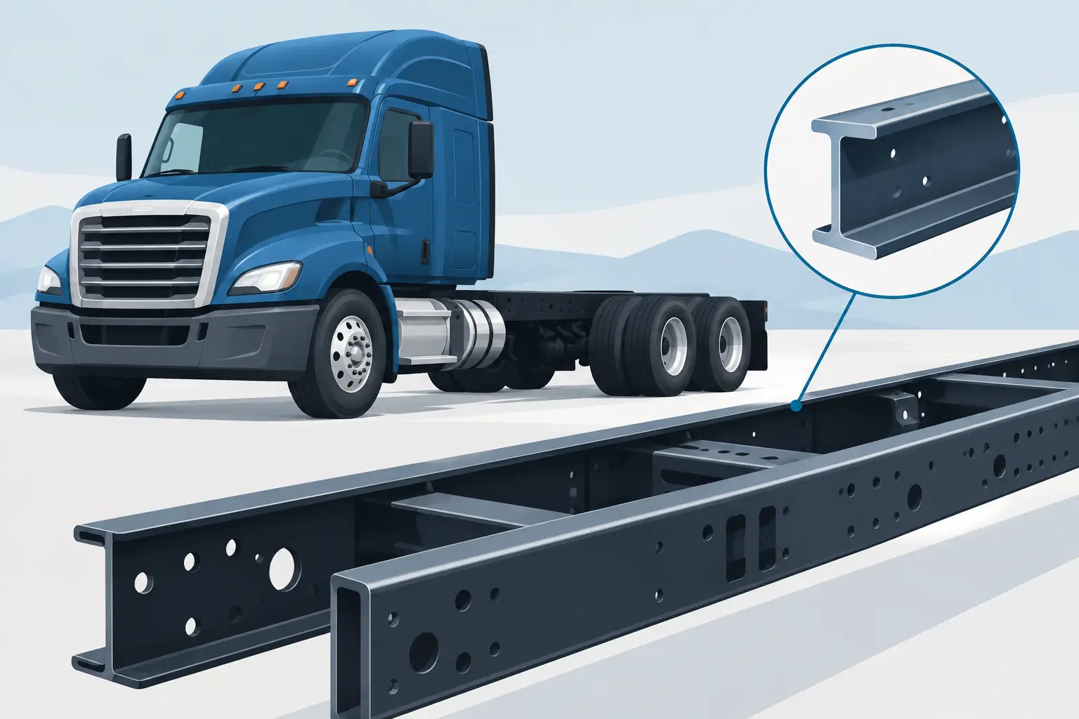
A frame rail drawing can look complete while still leaving the fabricator to make decisions that affect fit-up, strength, repeatability, and cost. Knowing how to specify frame rails means defining more than steel grade and overall length. For heavy truck programs, the specification must communicate the loading intent, formed geometry, hole pattern control, interfaces, weld requirements, inspection plan, and production quantity.
The objective is not to over-dimension every surface. It is to give the manufacturer clear, usable requirements for producing long structural members that assemble consistently with crossmembers, brackets, suspension components, powertrain mounts, and body equipment.
How to specify frame rails from the functional requirements
Start with the rail’s job in the vehicle or subassembly. A heavy truck rail may carry concentrated loads from suspension brackets, fifth-wheel structures, equipment bodies, outriggers, battery boxes, tanks, or crossmember connections. The rail may also need to manage torsional loading, bending loads, fatigue exposure, and mounting access over a long length.
These functional conditions should drive the drawing and the purchasing package. Identify the intended application, mating components, critical load zones, and any areas where drilling, welding, or field modification is prohibited. If the rail is part of a heavier welded assembly, define whether it is supplied as a formed blank, a drilled and trimmed rail, or a complete welded subassembly.
Material should be called out by the applicable standard, grade, thickness, and any required condition. If equivalent material is permitted, state the acceptance criteria rather than assuming substitutions will be understood. Mechanical-property requirements, coating preparation needs, and customer-specific traceability requirements should also be identified when applicable.
A material designation alone does not establish whether a specific rail can be formed without cracking, distortion, or unacceptable springback. That review depends on the drawing geometry, bend radii, material condition, grain direction where relevant, thickness, and required section profile.
Define geometry with clear datums and control zones
Long rails are sensitive to accumulated variation. A small change in web height, flange angle, rail sweep, or hole location can create assembly problems farther down the chassis. The drawing should establish a datum strategy that reflects how the rail will be located during fabrication and how it will be measured during inspection.
For a typical C-channel or formed rail, this may include a primary datum on the web, a secondary datum at one end or a defined station, and a tertiary feature that establishes orientation. The best datum scheme depends on the assembly, but it should allow both the supplier and the receiving plant to evaluate the same part in the same way.
Define overall length, cut-end condition, web depth, flange width, section angles, formed radii, and any intentional sweep, camber, or taper. For profile rails, use section views at meaningful stations instead of relying on a single general view. If the rail has changing geometry, identify the transition locations and how those locations are controlled.
Not every dimension needs the same tolerance. Reserve tighter controls for features that govern assembly, such as mounting faces, crossmember interfaces, suspension locations, and matched rail pairs. Broader tolerances may be appropriate for non-mating edges or areas later covered by equipment. This distinction helps avoid specifying inspection effort that does not improve vehicle function.
Control hole patterns by function, not only by coordinates
Hole patterns often determine whether a frame rail will assemble correctly. Specify hole diameter, shape, thread or non-thread condition, counterbore or countersink requirements, and positional relationship to the defined datums. Clearly distinguish production holes from pilot, fixture, handling, or shipping holes.
For repeated hole patterns, provide station dimensions and identify the controlling reference edge or datum. When holes are intended to locate brackets or crossmembers, their positional requirements may need to be more stringent than holes used only for clips or routing hardware. If holes are added after forming, state that requirement. If they are cut before forming, the supplier should evaluate how the process sequence affects their final location.
Avoid relying on note-only instructions such as “match drill as required” unless the receiving assembly process is defined. That instruction can transfer variation and rework downstream instead of controlling it at the rail manufacturing stage.
Specify forming requirements that match the rail profile
Heavy truck frame rails commonly require long, repeatable forming operations. The selected process must account for material thickness, rail length, flange geometry, bend locations, and the allowable condition of the finished surface. Forming sequence also affects access for laser cutting, drilling, welding, and dimensional inspection.
IONSA operates a 2,400-ton CNC press brake with a 53-foot forming length. Those equipment ratings are relevant when evaluating long chassis rails and heavy fabricated structures, but drawing-specific feasibility still requires review of the rail profile, material, bend requirements, tooling, and quantity.
Call out formed radii where they are functionally required. If the design permits a range, state the acceptable range rather than forcing an unnecessary nominal value. Define whether slight springback is acceptable and which surfaces or angles are critical after forming. For rails that must nest with another component, use a practical functional check or profile requirement that reflects the actual interface.
A 30 kW fiber laser with a 16-meter cutting bed can support long-part cutting before or after other process steps, depending on the part design. However, the presence of long-bed cutting equipment does not eliminate the need to define cut quality, edge condition, hole requirements, and inspection criteria on the drawing.
Address welding as part of the assembly definition
Many frame rail programs include reinforcements, fish plates, brackets, crossmembers, gussets, or other heavy truck subassemblies. When welding is required, the drawing package should identify joint details, weld symbols, weld size, extent, sequence constraints where necessary, and surfaces that must remain free of weld or spatter.
The design should also account for distortion. Long rails can move during welding, particularly when attachments are concentrated on one side or in a localized area. If straightness, squareness, or bracket position after welding is critical, define the final acceptance condition rather than only the pre-weld component dimensions.
Weld requirements should align with the applicable code, customer standard, and service conditions. IONSA has more than 150 welding stations and an in-house AWS Certified Welding Inspector. The AWS CWI supports internal inspection activity; it does not mean that every weld receives identical inspection or independent third-party certification. Define the required visual, dimensional, nondestructive, or customer witness requirements for the specific program.
Build inspection and traceability into the purchase requirement
A frame rail specification should state what evidence is required at shipment and at what production stage it is collected. This may include material certifications, first-article records, dimensional reports, weld inspection records, coating documentation, and part identification requirements. The appropriate level depends on the vehicle application, customer quality system, production volume, and risk associated with the feature.
For long, complex rails, an agreed dimensional inspection plan is often more useful than a generic request for a “full inspection report.” Identify the critical stations, hole groups, formed profiles, and assembly interfaces to be measured. Creaform dimensional inspection equipment can support inspection under an agreed plan, but the plan should define the features, datums, reporting format, sampling frequency, and acceptance criteria.
If traceability is required, specify the traceability unit: heat, coil, blank, rail, batch, or shipment lot. Production records supported through MIETrak ERP can be structured around program requirements, but traceability depth should be established during launch rather than assumed.
For programs with rail-industry requirements, AAR M-1003 quality assurance certification may be relevant within its defined facility and activity scope. Do not treat a certification as a substitute for the actual drawing, inspection, and documentation requirements of the part.
Review manufacturability before releasing the rail
The best time to resolve rail manufacturability is before issuing a production purchase order. Provide the latest drawing revision, 3D model when available, material specification, annual and release quantities, target delivery schedule, part dimensions, component weight, and inspection requirements. Include mating-component information when hole patterns, bracket locations, or rail geometry depend on the larger assembly.
A supplier review should address whether the rail can be cut, formed, welded, handled, inspected, and packaged in a repeatable sequence. It should also identify where design choices affect cost or risk. For example, tighter hole position controls may be justified at suspension interfaces but unnecessary at nonstructural mounting locations. A welded reinforcement may improve stiffness but add distortion control and inspection requirements. A longer one-piece rail may reduce joints but introduce handling and shipping considerations.
For OEM teams sourcing in the United States or Mexico, IONSA can review heavy truck frame rail and heavy truck subassembly packages against material, geometry, production, and quality requirements. Submit drawings, material, quantity, dimensions, weight, schedule, and inspection requirements through the IONSA request-a-quote process so the manufacturing review is based on the actual part rather than assumptions.
A usable frame rail specification gives engineering, purchasing, quality, and manufacturing the same definition of an acceptable rail. That clarity is what supports repeatable fabrication and a chassis that fits together as intended.