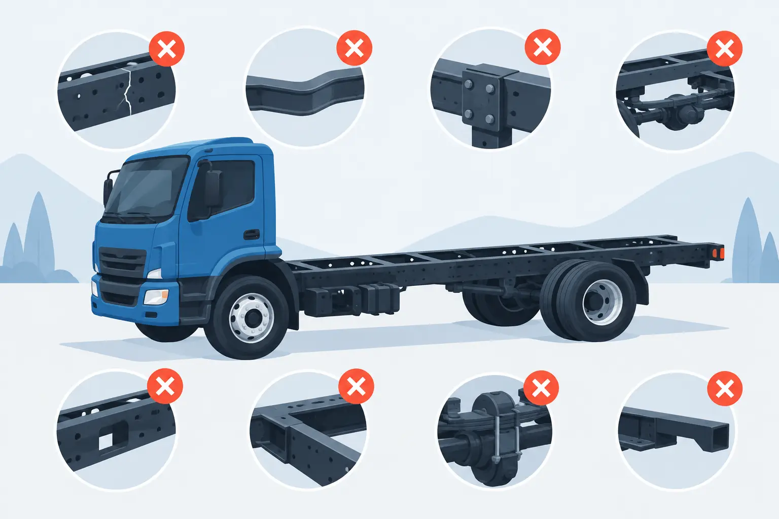
A heavy truck frame rail can look straightforward on a drawing: long formed steel, holes, brackets, and weldments. In production, however, small specification gaps can become expensive fit-up problems across a chassis assembly. The top truck frame design mistakes usually begin before cutting or forming, when load paths, datums, forming limits, weld sequencing, and inspection requirements have not been resolved together.
For OEM engineering, sourcing, and quality teams, the goal is not simply to procure a rail that meets nominal dimensions at one stage. It is to produce a repeatable component that can be formed, welded, inspected, coated if required, transported, and assembled without creating downstream variation.
1. Designing around nominal dimensions instead of functional datums
A rail drawing may define overall length, flange width, web height, and hole locations, yet still leave the manufacturing team without a clear dimensional control strategy. This happens when every feature is dimensioned from a different edge, or when the drawing does not identify the surfaces and features that control assembly.
Functional datums should reflect how the rail locates to crossmembers, suspension components, powertrain mounts, and cab or body interfaces. Hole patterns may need to be controlled from a shared datum rather than from each end of a long rail. This reduces tolerance stack-up and gives both the fabricator and the receiving plant a common basis for inspection.
The same principle applies to heavy truck subassemblies. If brackets are located from a formed flange that varies after forming, their placement can drift even when the bracket fixture itself is correct. Identify primary, secondary, and tertiary datums early, then align fixture design and inspection planning to those references.
2. Ignoring how material behavior affects formed rails
Long frame rails are not only cut parts. They are formed structural members, and steel grade, thickness, grain direction, bend radius, springback, and forming sequence all affect the finished profile.
A specified inside bend radius that is too tight for the selected material can increase cracking risk or create excessive variation. A design that assumes perfectly sharp corners may also be difficult to achieve consistently. Conversely, an unnecessarily large radius can affect mating components and packaged clearances.
Forming feasibility is drawing-specific. A 2,400-ton CNC press brake with a 53-foot forming length provides substantial capacity for long, heavy components, but its rating does not establish that every rail geometry, material grade, bend sequence, or tooling requirement is feasible. The manufacturing review should consider developed length, bend locations, return flanges, part handling, and the relationship between holes and bends.
3. Placing holes too close to bends, edges, or high-stress areas
Hole location is one of the most common causes of avoidable rework. Holes placed too close to a bend can distort during forming, shift from their intended position, or become difficult to gauge. Holes close to a cut edge can also reduce local strength or complicate downstream fastening.
The question is not whether a hole can be laser cut. It is whether the final hole location and shape will remain acceptable after forming and through the full assembly process. This is particularly relevant for long rails with dense hole patterns, access openings, or slots used for mounting brackets and crossmembers.
Engineers should also distinguish between holes serving a temporary manufacturing purpose and holes required by the finished vehicle. Lifting, locating, or fixture holes may be useful, but they need ownership, a defined disposition, and a clear rule for whether they remain in the final component.
4. Treating welds as an afterthought
A frame rail assembly often includes brackets, reinforcements, gussets, crossmember interfaces, and other welded details. If the weld design is released without considering access, sequence, restraint, and inspection, the assembly can develop distortion that compromises critical interfaces.
Weld location should follow the structural load path, but it must also allow a practical welding approach. Tight cavities, blocked access, and weld calls that require difficult positions can affect consistency and cycle time. Intermittent welds, continuous welds, weld size, start and stop locations, and cosmetic requirements should be explicit where they matter.
Weld sequence deserves equal attention. Heat input can pull a long assembly out of straightness or change flange relationships. Fixtures can manage movement, but they do not eliminate the physical effects of welding. A production-ready design accounts for controlled sequence, fixturing strategy, and measurement after welding.
IONSA supports welding through more than 150 welding stations and an in-house AWS Certified Welding Inspector. The AWS CWI role supports welding inspection within the facility; it should not be interpreted as independent third-party certification of every weld. Acceptance criteria, inspection extent, documentation needs, and any customer-specific weld procedure requirements should be established for each program.
5. Underestimating distortion across a long component
Long rails magnify small movements. A minor flange change at several forming stations, combined with local weld shrinkage and handling effects, can create a final condition that is difficult to correct without affecting other dimensions.
This mistake often appears when drawings specify only local features but omit global requirements such as straightness, twist, camber, or parallelism. These requirements should be tied to functional need. Overly restrictive controls can add unnecessary manufacturing burden, while missing controls can leave the supplier and customer debating acceptability after parts arrive.
A practical inspection plan defines what is measured, when it is measured, what datum structure applies, and how results are recorded. Creaform dimensional inspection equipment can support dimensional inspection under an agreed plan. The measurement method, coverage, reporting format, and acceptance limits should match the program requirements rather than relying on assumed capability.
6. Specifying material without considering procurement and processing
A material callout must do more than identify strength level. It should establish the applicable grade or standard, thickness, condition, test-report expectations, coating condition if applicable, and any directional or surface requirements relevant to forming and welding.
Material substitutions should not be assumed to be equivalent. Two steels may appear similar in strength yet respond differently during forming or welding. If the rail design relies on a particular bend radius, fatigue performance, or weld procedure, the approved material path should be clear before production release.
For sourcing teams, this is also where quantity and schedule matter. Prototype, pilot, and serial-production volumes can require different approaches to material nesting, tooling, fixtures, and inspection. A 30 kW fiber laser with a 16-meter cutting bed can support processing of long components, but final process planning depends on the part geometry, material, quantity, and required production schedule.
7. Leaving corrosion protection disconnected from the design
Coating requirements affect more than appearance. They can influence hole sizing, drainage provisions, masking needs, weld cleanup, surface preparation, and the order of fabrication operations. Boxed or partially enclosed sections may trap moisture or process fluids if drainage and venting are not considered.
Customer specifications should state the coating system, preparation requirements, coverage expectations, repair approach, and any performance standard that applies. For pad-mounted equipment enclosures, for example, IEEE C57.12.28 may be relevant when specified by the customer, but it should not be treated as a blanket certification for unrelated fabricated products.
Truck frame rails and subassemblies need the same discipline: define the required corrosion protection for the end-use environment, then confirm that the fabrication design supports it.
8. Sending incomplete information to the manufacturing review
The fastest way to create late changes is to release a drawing package that lacks assembly context. A fabricator needs more than a PDF profile to evaluate a heavy truck frame rail. Three-dimensional models, weld symbols, material specifications, critical characteristics, quantity assumptions, packaging expectations, and inspection requirements all affect the manufacturing approach.
Production traceability should be defined at the program level as well. MIETrak ERP supports production records, but the required traceability depth depends on the customer program, the materials involved, and the documentation specified in the purchase order. Quality assurance requirements should be reviewed with the same care as geometry and welding requirements. AAR M-1003 certification applies to defined quality assurance facility and activity scope, not automatically to every product or customer requirement.
For buyers reviewing heavy truck frame rail and subassembly suppliers, capability should be connected to the actual drawing package. IONSA’s heavy truck frame rail and subassembly manufacturing capabilities combine long-part laser cutting, 53-foot press brake forming, welding capacity, and dimensional inspection support for an engineering-informed review.
Before releasing the next rail design, submit drawings, material requirements, quantity, dimensions, component weight, schedule, and inspection requirements for review. Early manufacturing input is often the most direct way to prevent a drawing detail from becoming a production problem.