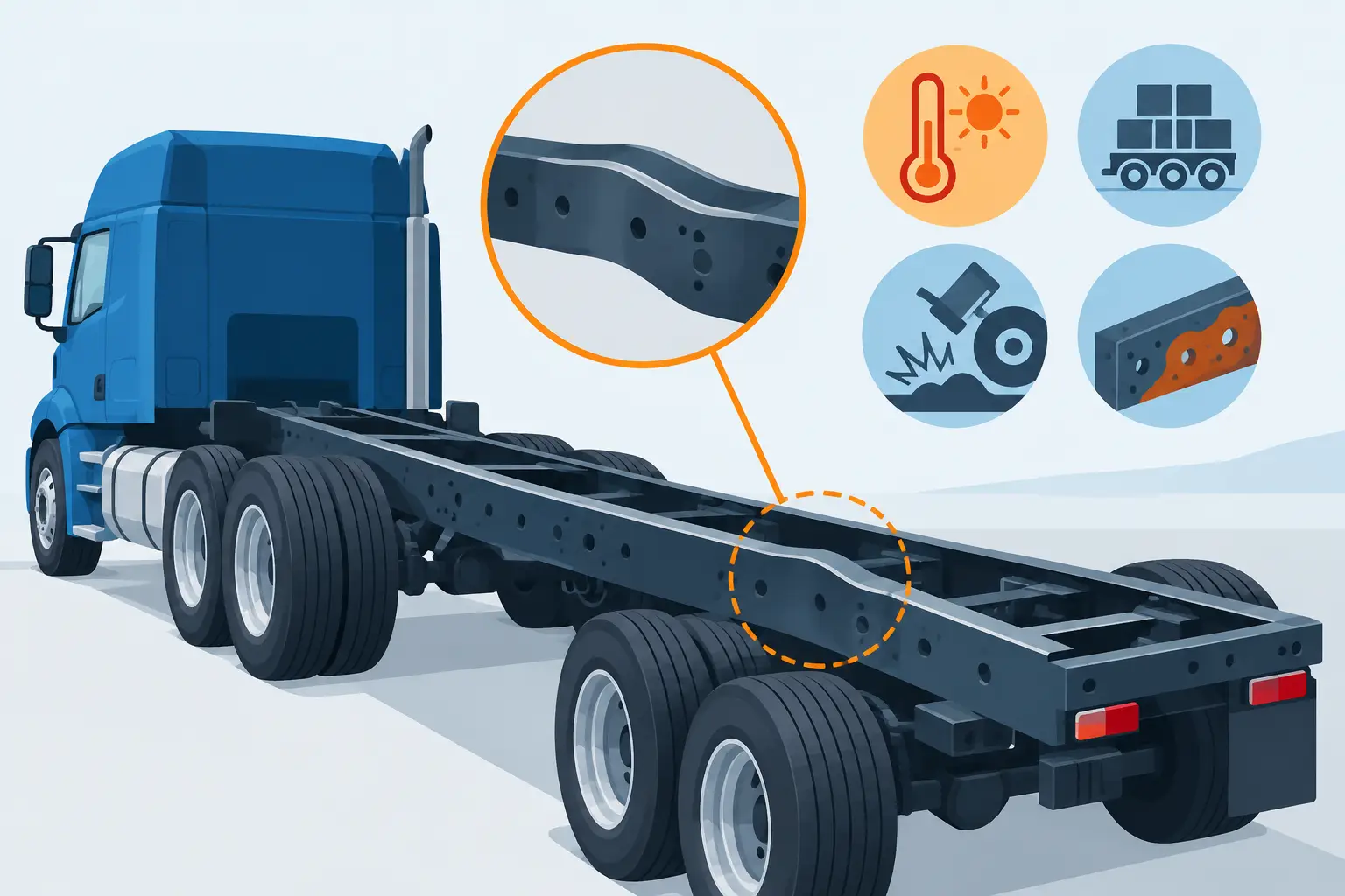
A long heavy truck frame rail can leave a forming operation within its intended profile and still move enough during welding, cooling, or handling to create an assembly problem. For OEM teams, the question of what causes frame rail warpage is not limited to one process. It is usually the accumulated effect of material condition, formed geometry, localized heat, fixture strategy, and the order in which the rail is built.
Warpage matters because frame rails establish critical mounting relationships for crossmembers, brackets, suspension components, powertrain supports, and body or equipment interfaces. A rail that looks acceptable before assembly can become difficult to locate, weld, inspect, or mate with its counterpart after subsequent operations. Prevention starts with identifying where residual stress enters the process and controlling it before a correction operation becomes necessary.
What causes frame rail warpage during fabrication?
Frame rail warpage is a dimensional change caused by uneven stress or uneven strain through the length, width, or thickness of the part. It can appear as sweep, camber, twist, flange movement, local buckling, or a change in hole-to-feature position. The visible condition depends on the rail design and the manufacturing sequence.
Forming stress and springback
Press brake forming introduces plastic deformation into the bend zone. Once the tooling releases the part, the material elastically recovers to some degree. This is springback, and it is an expected condition that must be accounted for in the forming plan.
Springback is not always uniform. Material grade, thickness variation, coil direction, yield strength, bend radius, and flange geometry can all affect the final angle and section shape. On long rails, small variations repeated over multiple bends can create a meaningful change in overall straightness or twist.
A 2,400-ton CNC press brake with a 53-foot forming length can support long-part forming, but equipment capacity alone does not establish drawing feasibility or final dimensional performance. The tooling arrangement, rail geometry, material condition, bend sequence, and required inspection plan must be reviewed against the customer drawing.
Welding heat input and shrinkage
Welding is one of the most common sources of rail distortion. As weld metal and adjacent base metal heat up, they expand. As they cool, they shrink. When that shrinkage is restrained or concentrated on one side of the rail, it can pull the component out of position.
Longitudinal welds may contribute to sweep or camber. Transverse welds, bracket welds, and crossmember attachments can create local bowing or flange movement. Welds placed asymmetrically across the rail section can also induce twist, especially when the assembly is released from a fixture before it has cooled sufficiently.
The effect is not simply a matter of weld size. Heat input, travel speed, weld sequence, joint design, tack placement, interpass temperature, and the amount of restraint all influence distortion. A larger weld is not automatically worse, and a smaller weld is not automatically safer. The controlling factor is whether the approved welding procedure and sequence produce the required joint while keeping dimensional movement within the project’s acceptance criteria.
Material variability and residual stress
Steel arrives with its own history. Rolling, leveling, cutting, storage, and previous forming can leave residual stresses in plate or coil. Once material is laser cut, formed, or welded, those stresses can redistribute and cause movement.
This is particularly relevant when rails include long narrow profiles, large openings, closely spaced holes, or uneven material removal. Cutting features can release stress in a way that changes the part’s shape before it reaches forming or welding. Material substitutions, even within an allowed specification range, should also be evaluated because mechanical properties affect springback and welding response.
A 30 kW fiber laser with a 16-meter cutting bed provides capacity for long components and nested rail blanks. However, cutting strategy should be treated as a process variable. Lead-in locations, cut order, part support, tab strategy, and the sequence of large openings can affect how a long blank behaves after cutting.
Fixture design, clamping, and release timing
Fixtures are meant to locate a part, but they do not remove the forces created by welding and cooling. If a fixture is too light, it may allow the rail to move during welding. If it restrains the assembly without considering thermal movement, stress can remain locked into the structure and appear when clamps are released.
The timing of release is equally important. Releasing a hot or partially cooled assembly can allow movement that is not visible while the rail remains clamped. Conversely, excessive clamping force can mark the material, complicate loading, or introduce local deformation. The right approach depends on rail section, weld locations, component mass, and the specified dimensional controls.
Handling and unsupported storage
A rail can be manufactured correctly and then distorted by poor material handling. Long components require support at planned locations during transfer, staging, and shipment. Lifting a rail from only two points may allow deflection under its own weight. Forklift handling can damage flanges or create local bends if fork spacing and load support are not appropriate.
Storage matters as well. Uneven dunnage, stacking without defined support points, or placing heavy subassemblies on top of rails can introduce distortion after inspection. For heavy truck subassemblies, handling instructions should be part of the production plan rather than an afterthought at shipping.
Distinguishing rail warpage from a tolerance issue
Not every dimensional deviation is warpage. A formed angle that is consistently outside specification may point to springback compensation or tooling setup. A feature location that shifts only after bracket welding may indicate weld shrinkage. A rail that varies from part to part can suggest material inconsistency, fixture repeatability, or handling variation.
The distinction matters because the corrective action must match the cause. Straightening a finished rail may address the immediate condition, but it does not necessarily prevent recurrence. Rework can also add cost, affect coating preparation, alter residual stress, and complicate traceability if it is not controlled within the manufacturing plan.
Controls that reduce frame rail distortion
The most effective programs control distortion across the complete process route. They begin with manufacturability review, not final inspection. Drawings should clearly identify datums, profile requirements, straightness or flatness requirements, critical hole patterns, welded attachments, and any inspection sequence requirements.
Before production, the manufacturer should evaluate the rail blank, bend sequence, tooling, weld access, fixture approach, and expected movement during cooling. For assemblies with demanding dimensional requirements, a first-article or pilot build can help establish a repeatable process before full production quantities begin.
During production, practical controls typically include balanced welding where design permits, defined tack and weld sequences, controlled clamping, documented handling points, and inspection at meaningful stages. Measuring only the completed rail can identify a problem too late. In-process checks after forming, before welding, after major welded attachments, and after release from fixtures can isolate the stage where movement occurs.
Dimensional inspection should be aligned with the drawing and agreed quality plan. Creaform dimensional inspection equipment can support measurement of large fabricated components under an agreed inspection plan. The required inspection coverage, reporting format, datum strategy, and traceability depth should be established for the program rather than assumed.
For welded heavy truck frame rails and subassemblies, welding quality oversight also needs to be connected to dimensional control. IONSA’s in-house AWS Certified Welding Inspector supports welding inspection activities, while the production plan determines the applicable weld procedures, inspection points, and documentation for a given program. MIETrak ERP can support production records, with traceability depth defined by program requirements.
What buyers should provide during supplier review
Frame rail distortion risk can be assessed more effectively when the sourcing package includes the information that drives process planning. At minimum, buyers should provide:
- Current drawings with revision level, material specifications, dimensional tolerances, weld symbols, and datum scheme.
- Annual and release quantities, including prototype, pilot, and production expectations.
- Rail length, section geometry, component weight, and details of attached brackets, reinforcements, or crossmembers.
- Inspection requirements, including first-article expectations, measurement reports, special characteristics, and required records.
- Packaging, handling, coating, and delivery requirements that may affect the completed rail.
These details allow a fabricator to evaluate whether distortion can be controlled through forming, fixturing, weld sequencing, inspection, and handling, or whether the drawing and process assumptions need further engineering discussion.
The same discipline applies beyond truck rails. Transformer tanks, large freight rail components, and fabricated steel structures for data centers can all experience movement from cutting, forming, welding, and support conditions. The geometry and acceptance criteria change, but the governing principle remains the same: manage stress before it becomes a final-part dimensional issue.
For an engineering-informed review of a heavy truck frame rail or subassembly, submit drawings, material, quantity, dimensions, weight, schedule, and inspection requirements at https://ionsamx.com/#request-quote. A clear manufacturing review before release is often the most practical way to prevent warpage from becoming a production correction.